How to make simple key code lock switch circuit
In this project we learn how to make simple key code lock switch circuit easy at home using few simple steps with circuit diagram. in this project we use CD4017 IC. its best for this project.
 |
| homemade simple key code lock switch circuit |
for making this project we need some components.
Components:
- CD4017 IC
- IC Base
- 6V Relay
- 16v 100uf capacitor
- BC547 NPN Transistor
- Push Buttons (10)
- 1K Resistor
- 10K Resistor
- 100K Resistor (2)
- 1N4007 Diode
- 1N4148 Diodes (5)
- LED
- 9V Battery
- Battery Clip
- PCB Board
- Soldering Iron
- Soldering wire
CD4017 basically counting base ic. we can use it for low range counting projects.
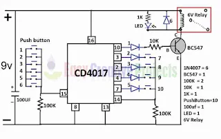
Key Code Lock Switch Circuit Diagram:
- CD4017 IC has 16 pins.

simple key code lock switch circuit diagram - Connect anode side of 1st 4148 diode with 10 number pin and cathode side connect with 10k resistor.
- and connect 2nd side of 10 resistor with base pin of BC547 transistor.
- now connect anode side of 2nd 4148 diode with 3 number pin and cathode side connect with push button.
- connect anode side of 3rd 4148 diode with 2 number pin and cathode side connect with push button.
- next connect anode side of 4th 4148 diode with 4 number pin and cathode side connect with push button.
- connect anode side of 5th 4148 diode with 7 number pin and cathode side connect with push button.
- now connect 14 number pin with 2nd sides of all push buttons.
- connect 100K resistor with 14 number pin.
- and 2nd side of 100k resistor connect with ground wire.
- and connect 8 number pin and 13 number pin with ground wire.
- connect 15 number pin with 100k resistor.
- and 2nd side of 100k resistor with ground wire.
- BC547 emitter pin connect with ground wire.
- and collector pin connect with 6v relay coil pin.
- 2nd side of relay coin pin connect with 16 number ic pin.
- 16 number ic pin use for positive power.
- connect 1N4007 diode with relay coil pins.
- now connect 1k resistor and LED with relay coil pins like diagram.
- connect 16v 100uf capacitor with positive and negative wire.
- and finally connect 9v power with positive and negative wire. ( positive wire connect with 16 number pin. and negative wire connect with 13 number pin.)
we learn it more batter with watching video.
Video of homemade key code lock switch circuit:
in conclusion its simple password security for electronic device using ic 4017 project. you can use it for any electronic project.


Post a Comment
Note: Only a member of this blog may post a comment.