How to make wireless phone set easy at home
In this project we learn how to make wireless phone set easy at home using a few simple step with circuit diagram. so this project divided in two parts. 1st part we make sending device circuit and in 2nd part we make receiving device circuit. This project work on radio fm frequency.
Before making wireless phone set project you need to learn these two project. then you can make this project very easily.
Before making wireless phone set project you need to learn these two project. then you can make this project very easily.
 |
| Homemade wireless phone set |
1st Part of wireless phone set:
in 1st part we make wireless phone sending device and circuit. using this circuit we can send our voice on wireless waves frequency.
Components:
- SN74LS13N IC
- IC Base
- Mic
- LM7805 Voltage Regulator(for 5v output)
- 104pf Capacitor
- 103pf Capacitor
- 22pf Capacitor
- 4.7k Resistor (2)
- PCB Board
- LED
- 9V Battery
- Battery clip
- Soldering wire
- Soldering iron
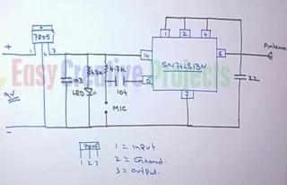
Wireless Sending Device Circuit Diagram:
 |
| Wireless sending device circuit diagram |
For sending device we use SN74LS13N IC for sending data. its convert our voice into radio signal. following few steps and make transmitter circuit.
- Connect 1,2,4, and 6 number pin with each other.
- now connect antenna with 6 number pin.
- connect 22 number capacitor with 6 and 7 number pin.
- connect 1st side of 4.7k resistor with 14 number pin.
- now connect 1st side of 104 number capacitor with 5 number pin.
- connect 2nd side of 4.7k resistor and 104 number capacitor with each other.
- now connect MIC with ground wire and 2nd side of 4.7k resistor.
- connect 4.7k resistor and LED with positive and negative wire.
- now connect 103 number capacitor with positive and negative wire.
- LM7805 has 3 pins.
- connect 9v positive wire with 1st pin of voltage regulator.
- now connect negative wire of 9v battery with 2nd pin of voltage regulator.
- voltage regulator 3rd pin use for 5v positive output.
2nd Part of wireless phone set:
In 2nd part we make wireless phone receiving device and circuit. using this circuit we can receive our voice from waves and convert into on speaker.
Components:
- TA2003P IC
- 16 Pin IC Base
- 15pf Capacitor
- 471pf Capacitor
- 4.7uf, 25v Capacitor
- 220uf 25v Capacitor
- 2pin 10.7MHz Ceramic Filter
- 3pin 10.7MHz Ceramic Filter
- Variable Capacitor or Tuner
- 26Gauge 4 turn and 5 turn coil
- PCB Board
- 2n2222a NPN Transistor
- 1K Variable resistor
- ON/OFF Switch
- Speaker
- Soldering wire
- Soldering iron ( how to make soldering iron)
Wireless receiving device circuit diagram:
 |
| Wireless receiving device circuit diagram |
For receiving device we use TA2003P ic this ic use for receiving signal from fm frequency. flowing few steps and make receiver circuit.
- TA2003P IC has 16 pin.
- connect antenna with 1 number pin.
- now connect negative power with 2 number pin.
- connect 3 pin ceramic filter with 3,6 and 8 number pin.
- 6 number pin use for positive power supply. (you can use 3v to 5v power supply)
- connect 5turn coin with 15 number pin and positive power.
- now connect 14 number pin with positive power.
- connect 15 number capacitor and 4 turn coil with 13 number pin and positive power.
- now connect 471 number capacitor with 11 number pin and positive power.
- connect 2pin ceramic filter with 10 number pin and positive power.
- now connect 9 number pin with emitter of 2n2222a transistor.
- connect speaker with collector pin of 2n2222a transistor and 3rd pin of variable resistor.
- 2nd pin of variable resistor connect with base.
- connect 220uf negative side of capacitor with 1st pin of 1K variable resistor.
- and positive side of capacitor connect with negative side of 4.7uf capacitor.
- and 2nd side of 4.7uf capacitor connect with 11 number pin.
Now combined both Parts:
sending device work on 5v power supply Now take a PCB board and connect sending device circuit components and receiving device circuit components.
 |
| Complete circuit diagram of wireless phone set |
- and receiving device also work on 5v power supply.
- so connect both parts power connection with 5v voltage regulator ( LM7805).
- now connect 9v power cell for input power. (Positive wire connect with 1st pin of LM7805 and negative wire connect with 2nd pin of LM7805)
 |
| Wireless phone sets |
now follow hole project and make 2 sets like picture. because you need 2 set for talking.
now adjust frequency using variable capacitor.
here we use variable capacitor. you can control sound using variable capacitor.
we learn it more batter with watching video.
Video of How to make wireless mobile phone set:
If you want to make it more advance so you can follow below link.
How to make wireless mobile phone with dialing number
How to make wireless mobile phone with dialing number


Post a Comment
Note: Only a member of this blog may post a comment.