How to make 5v adjustable current power supply
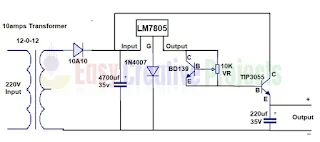
In this project we learn how to make 5v adjustable current power supply easy at home with the help of video and simple circuit diagram. in this project we also use LM7805 voltage regulator for regulate voltage. you can easily adjust current with variable resistor. For making this project we need some components,
Components:
- 24v or 12v 10 amps Transformer
- LM7805 Voltage regulator
- TIP3055 Transistor
- BD139 Transistor
- 35v, 220uf capacitor
- 35v, 4700uf capacitor
- 10A10 diode
- 10K Variable resistor
- Heatsink
- 1N4007 diode
- Soldering wire
- Soldering iron
- PCB Board
- Transformer has 2 side, 1st side called primary and 2nd side called secondary
- Primary side or primary winding use for 220v input power supply
- If you use 12-0-12 transformer then you can see 3 wires connection,
- Connect 10A10 diode with 1st wire of transformer.
- Now leave 2nd wire and 3rd wire use for ground wire,
- 35v, 4700uf capacitor has 2 pin,
- Positive pin connect with 2nd side of 10A10 diode and negative side connect with ground wire.
- Now input wire of LM7805 voltage regulator connect with 2nd side of diode
- 1N4007 diode connect with ground wire of voltage regulator and ground wire.
- Now collector pin of BD139 connect with output wire of voltage regulator,
- Variable resistor has 3 pin,
- Middle pin connect with base of bd139,
- 1st and 3rd pin connect with collector and emitter pin, like diagram,
- Now TIP3055 transistor base pin connect with emitter of bd139 transistor
- And collector pin connect with input pin of voltage regulator,
- Now positive side of 35v, 220uf capacitor connect with emitter pin of TIP3055 transistor,
- And negative side of capacitor connect with ground wire,
- Finally emitter pin of TIP3055 transistor use for positive output and ground wire use for negative output.
- 1st emitter
- 2nd collectors
- 3rd base
TIP3055 has 3 pin
- 1st base
- 2nd collector
- 3rd emitter
We learn it more batter with watching video.
Video of how to make 5v variable current power supply:
More related links


Post a Comment
Note: Only a member of this blog may post a comment.